In building the Upstairs Train, I ran into a number of problems and challenges due to its size and complexity. I pass on to you the lessons I learned in the hope that they will save you some time, frustration, and possible damage to your trains. These lessons fall into the following categories:
1. Preventing derailment when a switch is flipped the wrong way.
2. Independently running more than one train at a time in different "zones" when their tracks are interconnected.
3. Running a train in "mainline" mode through two or more zones.
4. Running more than one train around a single loop controlled by semaphores.
5. Preventing an engine from reversing directions after it has been stopped.
6. Designing a control panel that helps the operator keep it all straight.
After you read all that, read through the Summary, which ties it all together.
At present, when I operate in mainline mode, I limit myself to one train at a time on the mainline loop. That eliminates the possibility of a rear-end collision when one train runs faster than the other.
In zone mode, running two trains around a single loop isn't a problem because I can independently control the speed of each train to make sure that I never have more than one train in a given zone at once; I have to stay on my toes, but it can be done.
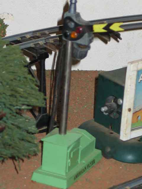
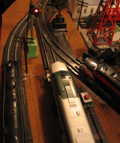
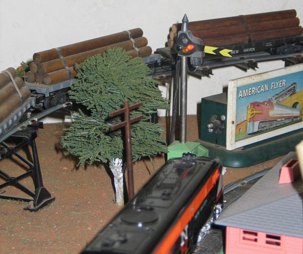
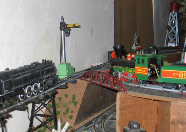
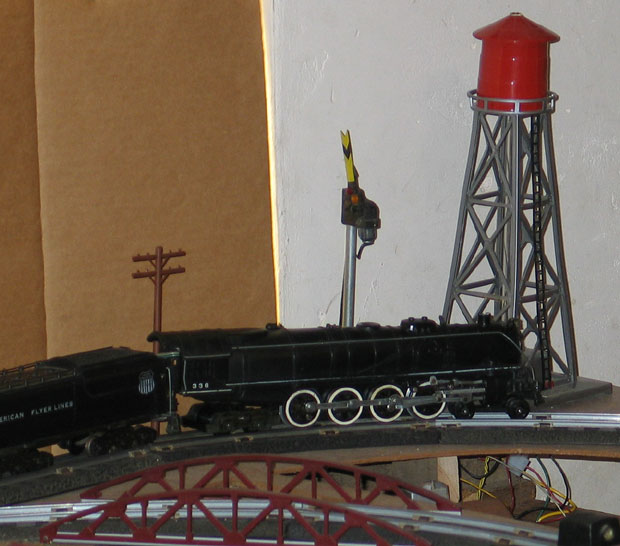
On a real railroad, a semaphore is a signal that tells the engineer to stop the train, like a traffic light for automobiles.On an American Flyer layout, however, a semaphore can be wired to proactively control a section of track so the train cannot pass the signal. The idea is to divide the loop into "blocks" with a semaphore at each block boundary. A train isn't allowed to enter a block if another train is already in the block. Having three semaphore blocks in a loop of track enables two trains to safely share a loop without gridlock. Similarly, four blocks enables three trains to safely share a loop, etc.
Special note: If you run a train with two powered engines, you'll have to wire them together so they each get their power from either engine. Otherwise, the first will stop running when it hits the isolated tracks, but the second will keep trying to push it ahead. Or the second may get stopped when a semaphore turns red and the first struggles to pull it out. It will be an interesting struggle!
The pins you buy today are plastic, not fiber. People still call them fiber pins because the original pins made by Gilbert were made of a fiber material. If you do find and use the original fiber pins, be careful when handling them, and when you handle the track after they're inserted. They break very easily. The new plastic ones bend a lot more before breaking. An inexpensive makeshift alternative is flat toothpicks shaved down to fit, but they break easiest.
In The Upstairs Train, there are three places where two or more tracks come together at a perfect place for the end of their blocks and the start of a new block. In that case, I use a single semaphore to control all the tracks that come together there. I end the block in the section of track AFTER the last switch (putting an insulating pin in it) and connect the white wire of the semaphore there. Three sections of track into each of the merging lines, I put an insulating pin in the base rail, which in some cases already has one to prevent derailment. (The exceptions are sidings in the railyard and Northeast Corner which don't need an insulating pin because they have no other source of power.)
Soon after a train leaves a block, you want to turn the semaphore red so a faster train following it can't run into it. (The device used to do this is called a "Track Trip." See below.) But don't put it too close to the semaphore or the train will get stopped when it turns the semaphore red! It depends on the type of Track Trip you use, but for most, it must be at least two sections of track out, and preferably three. And when the train is completely out of the block (or at least most of the way out), you can turn the preceding semaphore green so the next train can fill in the space it vacated.
The earlier #761 American Flyer semaphores came with two #697 Track Trips (see picture below), one to turn the semaphore red when an engine passed over it, and another to turn it green. The later #23761 Semaphores came with a two-button controller that relied on the operator to flip the semaphore red or green. The advantage of the track trips, of course, is automatic control, but a lot of people have trouble with them. Further, the 697s have to be flat on the table; they won't work on a trestle. And the track has to remain unsecured, not nailed down. I have been told that the track can't be held in rubber roadbed like The Upstairs Train, and I've also talked to people who have done it. After I do it, I'll update this page to let you know what I learn. The #23761 button relies on a fallible operator rather than a fallible device. Take your pick.
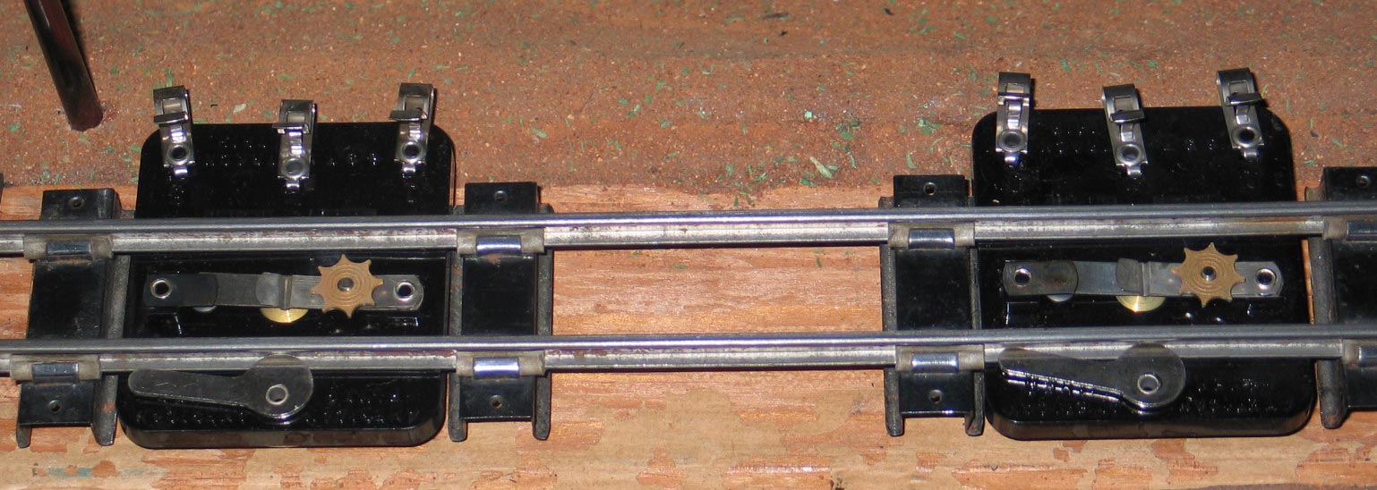
Alternative 3 is the #670 Track Trip (see picture below) made after the 697. It is connected to the track to electrically sense the passing of an engine. Its advantage over the 697 is that it can be used on my trestles but some people say it's not very reliable either, especially with dual-motor diesels, and it robs the engine of some of its power, which isn't good on an upslope. The two I got do not have that problem of robbing power; either I got great ones, or the problem is overstated. Or maybe it's because I have mine at the bottom of the slope before the engine starts struggling.
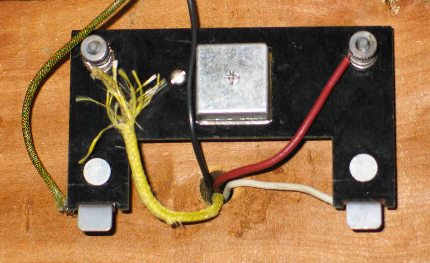
Note the small screw to the right of the shiny box in the middle. That enables you to adjust the sensitivity of the trip. I was able to adjust mine so the engine trips it but the light in a passenger car does not. That way, I can park a train with a car in that section of track and not burn out the semaphore coil. I am told that not all 670s have the adjusting screw; if you get one, make sure it has the screw.
The only trouble I've had with mine so far is that one sometimes sticks in the closed position, which keeps power to the semaphore and can burn it out. I need to find a solution to that!
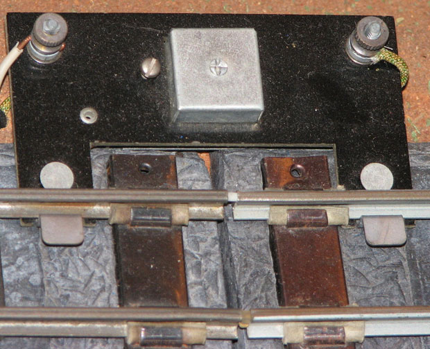
Here's what it looks like under the table. Simply connect wires where the Trip would clip onto the rail. To test the idea, I simply trapped the wire under the spring clip. After I was sure it would work right, I soldered in a connection.
You know how life works, though: after I gave up and went another direction, a solution emerged from other lessons learned. The problem seems to be getting the right combination of diode and capacitor to generate 12 volts DC for the relay. I haven't tried it yet, but I think the solution is to decouple the reed switch from the rest of the circuit. Power the reed switch from the track as in Tom's design, but pass 12VDC power from a bridge rectifier through it to the relay. No diode, no capacitor.
From Radio Shack:
275-206 DPDT relay
272-107 4.7mF 35W Capacitor
(increasing it to 20mF reduced
chatter, but it still isn't working
right)
276-1101 Diode
274-680 barrier strip for easy
connection
#26 enameled magnet wire wound
on a short section of a cocktail
straw to activate the reed switch
(part of a 278-1345B 3-pack)
From Mouser Electronics:
816-RI-01BAA reed switch
Many thanks to Carl Tuveson for talking me through the construction and troubleshooting process.
Alternative 6 is Tom Barker's do-it-yourself electric eye version of these infrared detectors. The advantage is space and price, but you have to create your own enclosure to make them fit in naturally.
After I got most of this written, someone passed me a reference to an S-Trains FAQ page by Tom Jarcho who used to write repair/service articles in S Gaugian magazine:
Flyer 670 pressure trip compared with 697 electromagnetic trip trips
697: pressure trip. Weight of passing train opens one contact, closes
another. Adjustable so loco only or any car sets it off, since locos are
heavier. Contacts may become bent ; try to straighten. Conatct points may
become dirty; clean with #600 sandpaper. Main problem: can go out of
adjustment and send power to solenoids when it isn't wanted or for too
long, burning out solenoid if for example a train is stopped over the trip,
or trip gets stuck. i use them a lot but they have to be watched all the
time. When used with rubber roadbed, cardboard must be placed under disc
to compensate for roadbed raising track approx. 1/16".
670: electromagnetic trip: power to an isolated rail section goes through
a coil which pulls contact closed when a loco is receiving power in the
isolated zone. Contact opens when track power is cut off. Some 670's are
adjustable to a degree w an adjustment screw; some are not. Problems: 1.
Not all that sensitive and accurate, often slow acting. Performance
depends to some extent on amount of track power at any given time (i.e. how
fast train is running). 2. causes power drop since the coil uses some of
the track power. Locos will slow or stall in the isolated zone, especially
2 motor diesels. Generally not good for use in reverse loops where
polarity is reversed by a track switch. Good in an area where you may want
to stop a train, since contact will open then and not burn out an
accessory.
Lockout eliminator: has nothing to do per se with track trips. Used with
train stopping accessories, esp the 761 semaphore. An isolated zone is
created to stop a train; with the semaphore, in the base post rail.
Lockout eliminator allows a trickle of electricity into this zone so the
reverse unit does not cycle. Sam the Sem, talking station have them built
in. New locos from LTI and AM will often creep in such a situation because
they use much less power than classic Flyer.
Hope this helps.
Tom Jarcho
With my plan in place, I started acquiring and installing the necessary semaphores, etc., in January of 2005. I soon learned, however, that I had only the beginning of a plan. I kept runing into other issues so it has been an evolutionary project.
When I started, I did know that I had one more problem to solve. The concept of a semaphore is to unblock a stopped train when the train ahead moves out of its block. That's easy to do as long as you don't have any switches between the train that moved and the blocked train. But I don't have any stretches of track that long. For example, if a train moves off my upslope, we can release the blocked train at the bottom of the slope IF the switch at the bottom of the slope would send the train up the slope. But if the switch is flipped the other way, it will send the train into the lower loop, which may hold a stopped train.
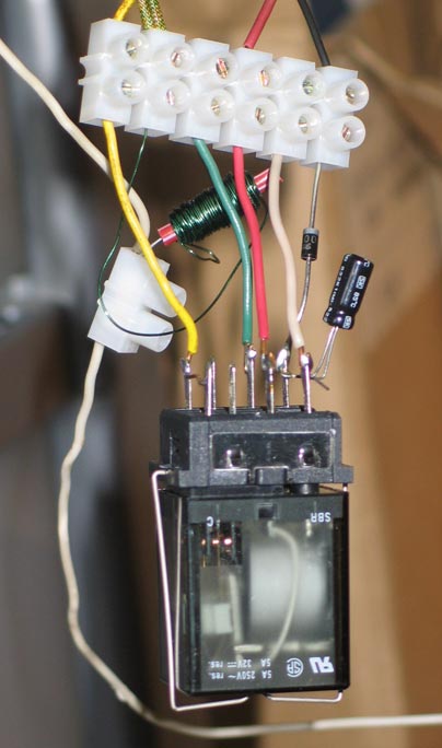
The solution I came up with was a set of double-throw latching relays that mirror the switches, and are activated by the same controls that flip the switches. When the switch flips to the red track, the corresponding relay flips to the red side because its coil is wired to the red terminal on the switch. Similarly, the relay flips green when the switch flips green. The electrical path through the relays mirrors the track path through the switches, so the signal from each track trip will go only to the appropriate semaphore. Neat solution if you have 18VAC relays, but it's easier to find hens' teeth.
I got suggestions from several people, but the breakthrough came when I was discussing DC operation with Tom Stoltz. He casually mentioned that DC has its advantages for switches. I picked up a #276-1146 Bridge Rectifier from Radio Shack and connected it to a 40-watt transformer that I only used for a couple of power accessories and light towers. As it turns out, there is a voltage drop from the Rectifier's AC in to the DC out, so connecting it to the fixed voltage post of the transformer gives me a nice steady 12VDC voltage source without giving up the variable control. I then connected a pair of switches to the resulting DC hookup. One switched fine, but the other buzzed without switching. I swapped the 40-watt transformer with the 50-watt that I use for lighting and got the same result.
Looking for alternatives, I realized that the 100-watt 8B transformer that I use to power trains in one of my four zones didn't have anything else on it but a couple of uncouplers. So I switched the bridge rectifier to it and now my switches change reliably.
Except for the pair that switch together. I have two lines through Union Station that come from the same mainline. One switch divides the mainline before the station and another rejoins them after it. Since I
always want them switched the same direction, I put both on the same controller. The 18VAC from my big 18B transformer handles them just fine, but 12VDC doesn't.
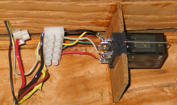
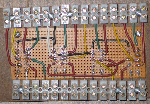
I now have most of my switches converted to 12VDC, so I got some double-throw latching relays to try out my concept. Here's a picture of the first four mounted and wired up for use at the Central Exchange. I like the flexibility that the European-style barrier strips give me in connecting, disconnecting, and rewiring things.
Next I realized that, even with that solved, I can't rely totally on this elegant automated solution. Suppose a train moves off the upslope in my example above, but then I flip the switch. The automated logic that unblocked the train at the bottom no longer applies. Manual override is required. So I concluded that I need the two-button controller from the #23761 Semaphore in addition to a track-trip solution. But my crowded control panel doesn't have space for six of those buttons, so I ordered six small SPDT center-off momentary contact toggle switches from Hosfelt Electronics. They're working fine for me.
The latest problem that I've run into is that the semaphores at the Northeast Corner and Lower Loop prevent me from doing switching operations in Union Station and the Rail Yard (respectively). As I move an engine into place, it trips the semaphore red and prevents itself from backing up! So I bought two on-off toggle switches to disable the track trips that control those semaphores.
Current status: All six semaphores are in place and wired to their overide switches. Five are wired them to their trips and two to their relays. Here are some pictures of them.

It takes time and money to maintain a website like this. If you would like to contribute financially to its ongoing success, you may send a contribution via PayPal using theupstairstrain@yahoo.com as the payee. Both credit card and direct transfers would be gratefully appreciated.
Trains Engines Operating Accessories Bridges Towers Buildings
Crossings Construction Landscaping Lighting Semaphores Control Panel
Wish List History Useful Links

